Description
- First worldwide fire & building authority approved animal facility alarm system
- Loud penetrating signal which alerts humans but has few detectable effects on animals
- Sound output of 97dB at 450mm
- CE Certified, manufacturer claims UL compliant, but not certified nor listed
- Operates at low voltages
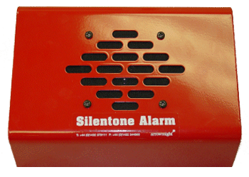
- Tough, durable, high impact powder-coated case
When a Silentone™ alarm is activated it generates a sound level of 97dB (measured at 450mm or greater peaks as measured in an anechoic chamber), at frequency between 430 and 470Hz. This is well within the human hearing range, yet mice and rats are not awakened or, if already awake, show no startled response, ear twitching or other indication or auditory disturbance. Rabbits and guinea pigs show little more than mild disturbance at this intensity and no observance response if the alarm is activated in a corridor of the animal house. For humans, however, the noise created by a Silentone™ alarm is intensely irritating and disturbing.
Specifications
Dimensions: W: 219 D: 140 H: 100
Sound Output: 97 db at 450mm
Voltage: 24V DC
Minimum Voltage: 10V DC
Wattage: 5W
DRAW: .3A per installed alarm
Compliancy rating: CE marked (electromagnetic compatibilty (EMC) Regulations 1992). Manufacturer states Silentone™ is UL compliant, however it is not UL listed. Their compliancy data, as well as our justification of request for variance, permitting Silentone’s installation is available upon request.
Case: Tough, durable, high impact powder coated case
Mounting: Wall plate mounted using pre-drilled holes
Installation: Internal terminal block
Installation
To fit to a wall; dismantle the alarm by removing the 4 screws which secure the backplate to the case. Using the backplate as a template, mark and drill the fixing holes in the wall (the alarm “footprint” is 219 mm wide by 100 mm high). Fix the backplate to the wall 3 or 4 mm diameter self-tapping screws (panhead type), into suitable wall plugs. Connect the unit to the 24v supply via the terminal block using twin core 0.5, 3 amp cable. Reassemble the alarm box to the base plate, ensuring the printed circuit board is at the top. Replace the 4 securing screws.